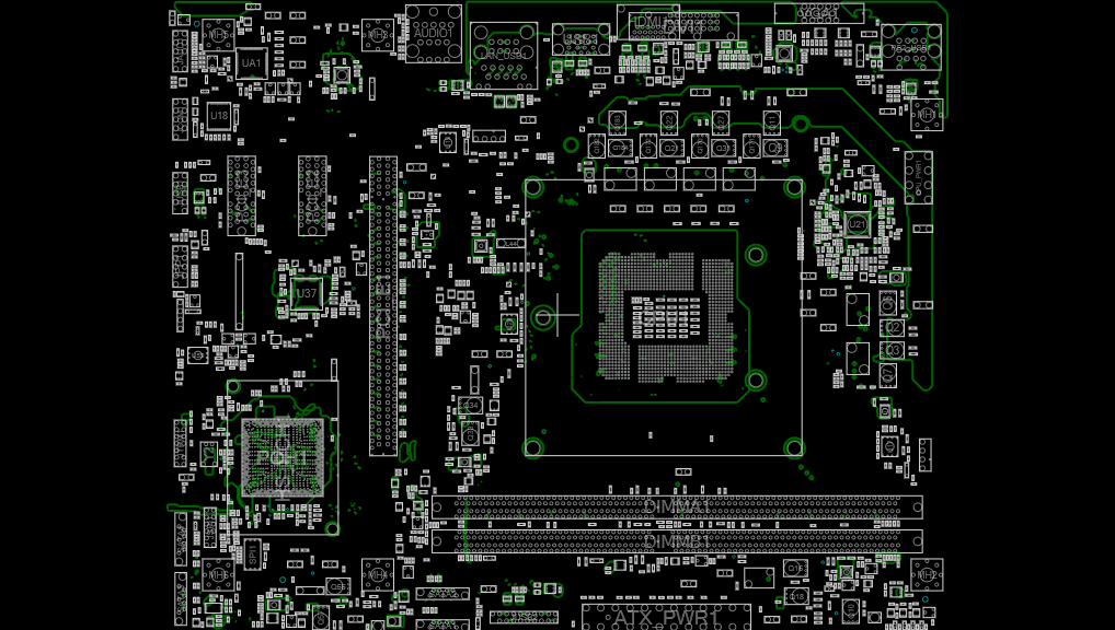
In the world of motherboard repair, detailed schematics are indispensable. These documents provide a clear, precise roadmap of the motherboard’s layout and components. Today, we are sharing the schematic for the MSI H310M PRO-VH PLUS (MSI MS-7C13) (Rev 10, 11). These schematics are invaluable for both professional technicians and hobbyists, offering critical insights into the motherboard’s design and functionality.
MSI H310M PRO-VH PLUS: Overview
The MSI MS-7C13 is a verastile motherboard designed to meet the needs of both everyday user. Here are its key features:
- Chipset: Intel H310
- Form Factor: Micro ATX
- Memory: Supports DDR4 2666MHz, up to 32GB
- Slots: 1 PCIe 3.0 x16, 2 PCIe 2.0 x1
- Storage: 4 SATA3 ports, 1 M.2 slot
- USB Ports: 4 USB 3.1 Gen1, 6 USB 2.0
- Audio: 7.1-Channel High Definition Audio
- Networking: Realtek 8111H Gigabit LAN
BIOS & FIRMWARE DOWNLOAD: H310M PRO-VH PLUS
Schematic Diagram
As a professional repair technician, I find these schematics incredibly useful. They provide a clear roadmap of the motherboard’s internals, making it easier to diagnose and fix issues. Whether you’re a seasoned pro or a hobbyist, these diagrams are a valuable resource.

The schematic diagrams for the MSI MS-7C13 are essential for anyone looking to repair this motherboard. These diagrams provide detailed information about the motherboard’s internal components and their connections.
Schematic Download
The schematic files are available in PDF format. You can access them using any standard PDF reader. Ensure your software is up-to-date to avoid compatibility issues.
Conclusion
I hope you find this article helpful! If you have any further questions or need additional details, feel free to ask. 😊
Disclaimer: The information provided here is based on available specifications and features at the time of writing. Always check the official product documentation for the most up-to-date details.


