
- Version
- Download 4
- File Size 0.00 KB
- File Count 1
- Create Date 2025-03-01
- Last Updated 2025-03-01
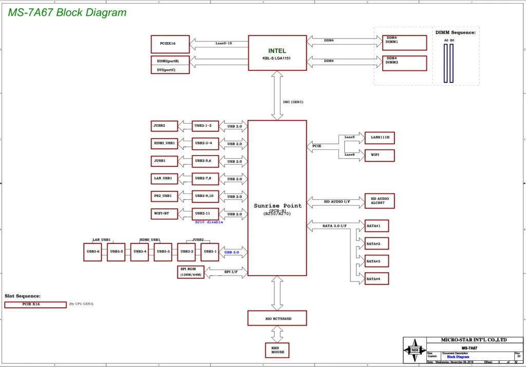
MSI B250I GAMING PRO AC (MS-7A67) (Rev2.0) Schematic
Ever struggled with a finicky motherboard? Schematics for the MSI B250I GAMING PRO AC (MS-7A67) are game-changers. These files map every trace and component, turning guesswork into precision. For techs, hobbyists, or curious minds, they’re your cheat sheet for repairs, upgrades, or mastering PCB design.
Motherboard Model & Key Features
The MSI B250I GAMING PRO AC (MS-7A67) Rev2.0 packs big performance into a mini-ITX frame. Here’s what makes it shine:
- LGA 1151 Socket: Supports Intel 6th/7th Gen CPUs like the i7-7700K.
- Dual-Channel DDR4: Handles up to 64GB RAM (2400MHz) for smooth multitasking.
- Turbo M.2 Slots: NVMe or SATA SSD support for blazing-fast storage.
- Onboard Wi-Fi/Bluetooth: 802.11ac and BT 4.2 for wireless freedom.
- RGB Fusion: Mystic Light Sync customizes your rig’s aesthetics.
- USB 3.1 Gen2 Type-C: 10Gbps transfers for modern peripherals.
BIOS & FIRMWARE DOWNLOAD: MS-7A67
Why These Schematics Matter (Straight From My Workbench)
Look, I’ve been there. Last month, a client’s MSI B250I wouldn’t power on. Without schematics, I’d waste hours tracing circuits. But with the boardview file? I spotted a corroded capacitor near the 12V rail in 10 minutes. No magic, just clarity. These schematics cut repair time in half—they’re non-negotiable for pros. Save your sanity and download them.
How to Use the Schematics Like a Pro
- Match Revisions: Confirm your board is Rev2.0—older versions differ slightly.
- Layer Navigation: Switch between power, signal, and ground layers for clarity.
- Component IDs: Cross-reference labels (e.g., “R120”) with the physical board.
- Multimeter Pairing: Test voltages/resistance against schematic values for accuracy.
Common Issues These Schematics Solve
- Dead USB Ports: Trace connections to pinpoint broken resistors or fuses.
- Boot Failures: Check CPU VCore circuitry for damaged MOSFETs.
- Wi-Fi Dropouts: Verify antenna solder points and RF module voltage.
- RGB Glitches: Diagnose LED controller ICs and signal paths.
Why Wait?
Grab the schematic, fire up your soldering iron, and turn that “dead” board into a victory. Tech repair is 10% mystery, 90% having the right map. 🔍
Legal Disclaimer
MSI does not publicly release schematics or boardview files. These resources are shared to aid responsible repair efforts. Always comply with local laws and avoid unauthorized distribution.
Struggling with a stubborn repair? Share your story below! 👇
#PCBRepair #TechCommunity
FAQs
How do I open the .pdf file?
You can access them using any standard PDF reader. Ensure your software is up-to-date to avoid compatibility issues.


