- Version
- Download 3
- File Size 0.00 KB
- File Count 1
- Create Date 2025-02-17
- Last Updated 2025-02-17
I’m thrilled to share a critical resource for tackling hardware issues on the ASUS FX507 laptop: the schematic and Boardview file (in .CAD format)! This file is compatible with tools like OpenBoardView, making it easy to visualize component layouts and trace circuits. Perfect for diagnosing power failures, GPU/CPU issues, signal errors, or faulty ports.
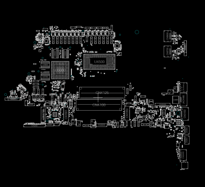
Why ASUS FX507 Boardview File Helps
- Circuit Analysis: Trace voltage rails (3.3V, 5V, 12V), identify faulty regulators, or debug charging circuit issues.
- Component Mapping: Quickly locate resistors, capacitors, ICs, or connectors using reference designators (e.g., R501, C202).
- Signal Debugging: Fix display, USB, or PCIe lane problems by tracking signal pathways.
- Software Compatibility: Open the .CAD file with free tools like OpenBoardView or paid alternatives like Altium 365.
FAQs
A Boardview file maps components to their physical locations on the motherboard. The .CAD format is widely used in repair communities to visualize circuits and troubleshoot without guesswork.
Use free software like OpenBoardView (cross-platform) or Altium 365 (cross-plataform). Load the .CAD file and cross-reference it with the schematic for precise diagnostics.
Ensure you’re using the latest version of OpenBoardView.
Verify the file isn’t corrupted (re-download if needed).
Check if your ASUS FX507 model matches the file’s revision.
No! This file is specific to the FX507 model. Using it for other devices may lead to incorrect repairs.
Schematics are proprietary, but repair communities share them for educational purposes. Avoid commercial misuse and respect copyright laws.
Use the schematic to locate power rails.
Cross-reference with the Boardview to check components (e.g., MOSFETs, capacitors) on the physical board.
Test with a multimeter in continuity/resistance mode.
Yes! Share feedback or corrections in the comments. Community collaboration ensures accuracy.
Key Notes
- Format: .CAD (compatible with OpenBoardView).
- Ethical Use: For education and repair only—no commercial redistribution.
Disclaimer:
This file is shared to support the repair community. ASUS does not publicly release schematics, so cross-check with official guides and comply with local regulations.
Found this helpful? Share your repair stories below! Let’s keep knowledge flowing. 🔧


