In this article, we delve into the ASRock Z97 EXTREME6 (Rev 1.02) motherboard schematics. These valuable files provide insights into the board’s intricate design, making them indispensable for hardware enthusiasts, repair technicians, and curious tinkerers. Whether you’re troubleshooting, planning modifications, or simply satisfying your curiosity, these schematics are a goldmine of information.
The ASRock Z97 EXTREME6 (Rev 1.02) Model
The ASRock Z97 EXTREME6 (Rev 1.02) is a feature-rich ATX motherboard designed for Intel’s 4th and 5th generation processors. Here are its key features:
- Connectivity: Gigabit LAN, USB 3.0/2.0, HDMI, DVI, and more.
- Socket Compatibility: LGA 1150 for Intel Core i7/i5/i3/Pentium/Celeron processors.
- Chipset: Intel Z97 Express.
- Memory Support: Four DDR3 DIMM slots supporting up to 32GB (DDR3-3200+).
- Expansion Slots: Multiple PCIe x16 slots, PCIe x1 slots, and legacy PCI slots.
- Storage Options: SATA III (6Gb/s) ports, M.2 slot, and eSATA.
BIOS & FIRMWARE DOWNLOAD: Z97 EXTREME6
Schematic Diagram
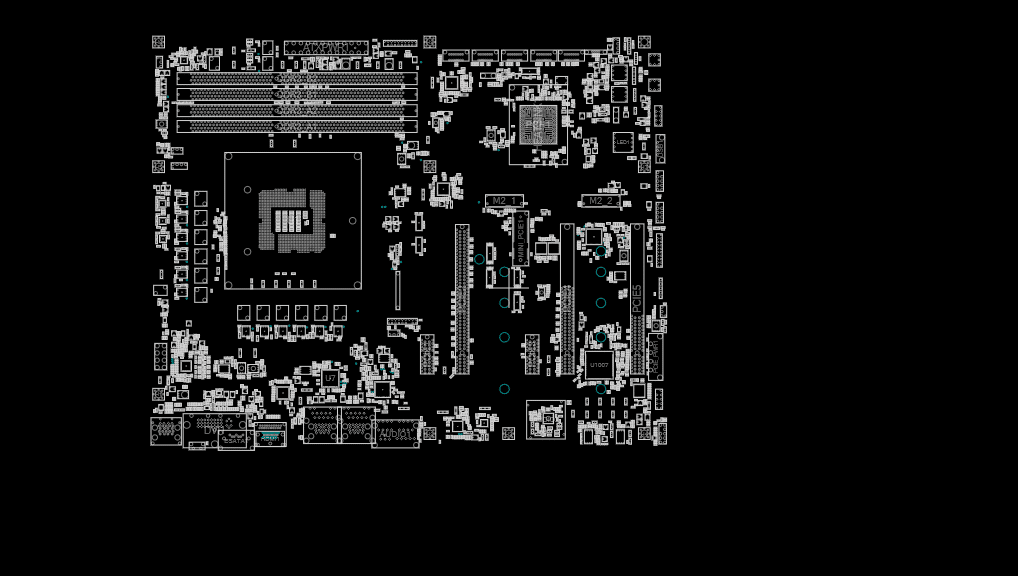
Download the ASRock Z97 EXTREME6 (Rev 1.02) schematics here. These diagrams reveal the intricate pathways of power delivery, signal traces, and component placement. Use them to identify components, trace signals, and troubleshoot issues.
Usage Instructions
When interpreting the schematics:
- Component Identification: Locate specific components (resistors, capacitors, ICs) using the reference designators.
- Signal Paths: Follow signal traces to understand data flow between components.
- Voltage Rails: Identify power supply lines and their connections.
Additional Notes
- VRM Design: The voltage regulator module (VRM) layout affects stability and overclocking potential.
- Signal Integrity: Pay attention to high-speed signal paths (e.g., PCIe lanes) for optimal performance.
- Component Footprints: Note the footprint sizes for replacement components.
Boardview Download
FAQs
Can I use these schematics for board repairs?
Is there a community forum where I can discuss Z97 EXTREME6 mods?
Conclusion
As an electronics enthusiast, I find these schematics fascinating. They unlock the motherboard’s secrets, empowering us to diagnose issues, optimize performance, and even design custom modifications. Remember, knowledge is power—use these schematics wisely!
I hope you find this article helpful! If you have any further questions or need additional details, feel free to ask. 😊
Disclaimer: The information provided here is based on available specifications and features at the time of writing. Always check the official product documentation for the most up-to-date details.


